PROCESSING OF GLASS REINFORCED THERMOPLASTICS
The addition of glass fibers to thermoplastics changes the processing guidelines for these materials. The following discussion is aimed at enabling you to mold the strongest parts possible by preventing fiber length attrition below the critical length .
1. Molding machine considerations
In-line reciprocating screw injection molding machines
work best for molding reinforced composites. Plunger type machines do not
provide uniform melt consistency or the same shot to shot accuracy that
a screw type machine provides.
The injection molder should be capable of injection
at pressures of at least 20,000 psi. An injection speed control valve is
desirable even though the fastest possible injection speed should be used
except where tooling limitations exist. Closed-loop control of barrel and
nozzle temperatures is also desirable.
General purpose type screws with compression ratios
of less than 3:1 are acceptable but lower compression screws help preserve
fiber integrity and reduce shear heating of the base resin. Screws with
a 2.0-2.5:1 compression ratio, and a minimum 18:1 L/D ratio are recommended.
A free flow non-return valve should be employed because it allows non restrictive
flow and lessens fiber damage. Positive shut-off valves should be avoided.
While injection pressures as high as 20,000 psi may
be necessary, tool life can be extended by using the lowest possible pressure
for each job. This also prevents flashing. A clamping force of 5 to 10
tons/in, of projected area of the part should be available; that is. 50
to 100% more clamping tonnage is necessary for a reinforced thermoplastic
than for a regular resin.
As with other molding jobs. 50-75% of the machine's
rated barrel capacity should be used.
2. What your auxiliary needs
will be
The essential material handling techniques for the
base resins also apply to the reinforced counterparts.
While the resin is packaged dry and in moisture-resistant
containers, hygroscopic materials (e.g., nylons, polycarbonates, polyesters,
etc. ) should be dried before molding with either a dehumidifying oven
or hopper. Since hot air has a higher moisture capacity, it is possible
to actually introduce moisture to a resin by using a circulating hot-air
oven. To prevent this, use dehumidifying equipment. If an oven is used,
spread the molding compound on trays at a depth of 1/2 in. or less and
dry at least four hours at the recommended temperature. (Oven or hopper
should be capable of maintaining a temperature of at least 250°F ±
5°F.)
It is occasionally necessary to dry even non-hygroscopic
resins to eliminate surface blemishes caused by moisture which has condensed
onto pellet surface.
Mold temperatures for reinforced resins will generally
be higher than for the non reinforced ones. Higher mold temperatures will
promote flow and give a better surface finish. A slightly higher mold temperature
will not increase cycle time. Standard mold temperature control equipment
is satisfactory.
The choice of temperature controllers will depend
on the resin being molded. For instance, oil or electric cartridge heaters
are needed when heating a mold for PEEK or PES where temperatures of 350°F
and 300°F, respectively, should be used. It's preferable to have independent
temperature control for each mold plate. This gives flexibility, especially
in long cores where it is often desirable to maintain each core at different
temperatures from the cavity.
When runner systems and rejected parts are reground,
any conventional scrap grinder may be used. Use a 3/8 in. to 1/4 in. screen.
As a rule of thumb, a maximum of 20% regrind can be blended with virgin
material with no appreciable loss of properties or color. If end use properties
are important or critical part tolerances are required, the use of any
regrind should be fully qualified prior to production. Be sure to keep
regrind free of contamination and dry before recycling. Blend regrind with
virgin material before adding it to hopper dryer.
3. Choosing a mold material
For extended production runs, hardened tool steels
are recommended. Select a mold steel that will provide the best combination
of abrasion and corrosion protection for the type of compound to be run.
Machinability should also be considered if a highly polished surface is
needed. Electroless nickel or chrome plating the mold surfaces will help
improve surface hardness, extend tool life, and provide additional corrosion
protection.
Aluminum, epoxy or P-20 steel materials are satisfactory
for prototype work.
Accelerated tool wear has sometimes been associated
with glass-reinforced thermoplastics. Few have been able to document any
case of excessive tool wear where proper mold design and processing conditions
were used with pre-dispersed glass fiber reinforced thermoplastic compounds.
Examples of conditions that can undesirably increase tool wear include
using un-dispersed glass fibers, excessively small gates, or use of soft
tool steels such as P-20.
4. Mold design factors
A Nozzle having an inside dia. of 7/16 to 1/2 in.
is recommended for most glass-reinforced thermoplastics. Exit orifice should
be 1/4 in. and the land should have a reverse taper of two to three degrees.
A reverse taper nozzle will provide a defined sprue break and reduce drooling
with low viscosity compounds.
A positive shutoff valve should be used only when
a low-viscosity resin like nylon is being molded at high melt temperatures
or when you are molding in a vertical machine.
The sprue bushing should be as short as possible and
have a taper of at least three degrees. The orifice should be slightly
larger than nozzle; that is, when using a 1/4 in. nozzle, sprue bushing
should have an orifice of 7/32 in. Of course, the radius of sprue bushing
and nozzle must match. Mismatch of these radii may cause sprue to hang
up in the mold.
The shortest possible runner systems should be used
and it should be polished to maximize flow.
In multi-cavity molds, where close part tolerances
are required, a balanced runner system is extremely important to achieve
part-to-part uniformity.
Size and location of gate (or gates) are the most
important factors in achieving a good molded part. General practice is
to gate into the thickest section of a part to minimize sinks or voids;
however, if surface finish is critical on a thin section, open the gate
into that section to maximize gloss.
In general, avoid a gate which directs melt against
a cavity wall or core pin because a gate of this type fractures the glass
fibers.
The number of gates used should be kept to the absolute
minimum necessary to fill the part in order to avoid weld lines that weaken
parts. If more filling capacity is necessary, enlarge the gate rather than
add additional ones.
The most widely used gate should be either full round
or rectangle. Specialized gates, such as diaphragm or flash gates, are
useful for special applications. The size of a round or rectangular gate
should be from two-thirds to the full width of the cavity wall. One advantage
of a rectangular gate is that, if more filling capacity is needed, gate
width may be widened without affecting freeze-off time.
Don t use small pinhole gates. A round gate should
not be less than 0.040 in. A good rule of thumb to follow is the larger
the molded part, the larger should be the gate except that the dia. of
a round gate should not exceed part's wall thickness.
The transition from runner to gate should be a blend
of gentle tapers rather than sharp angles to maintain highest possible
physical properties.
To keep pressure drop through the gates to a minimum,
keep lands short. Land lengths should be from 0.020 to 0.040 in.
Good venting of the cavity is essential for rapid,
uniform fill. For glass fiber reinforced resins which are low in viscosity
(like nylon), vents should be 0.001 by 0.025 in. wide. For a highly viscous
resin like polysulfone, vents of 0.004 by 0.200 in. wide can be used. The
most strategic locations for the vents are wherever air will be trapped
due to resin flow, i.e., at weld lines and the end of cavities. Vents should
be spaced about one inch apart along mold parting lines. Loose fitting
knock-out pins will also serve as vents. As for knock-out pins, large ones
or stripper plates should be used.
5. Part design factors
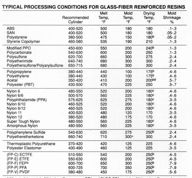
Typical shrinkage of glass fiber reinforced resin
will be one-third to one-half that of the non reinforced resin. Typical
shrinkage values for a variety of resins reinforced with 30% glass fibers
are given in the Table.
It is important to start with a prototype tool to
determine exact shrinkages, particularly to determine shrinkages of complex
parts which must be held to tight tolerances. Parts which have drastic
variations in wall thickness or which are molded of resins exhibiting anisotropic
shrinkages should be prototyped.
A non reinforced anisotropic resin (e.g., unfilled
nylon) will shrink more in direction of flow than in the axis transverse
to flow; however, when fiber glass is added to resin, glass fibers tend
to orient in flow direction; this limits shrinkage in flow direction. The
result: Glass fiber reinforced resins will shrink more along the axis transverse
to flow than along the axis of material flow.
Due to the lower shrinkage of reinforced resins, more
draft should be designed into the part to facilitate ejection from mold.
An angle of two to three degrees is recommended for core pins and cavity
walls.
Wherever possible, avoid designing undercuts which must be stripped from a mold.
6. Pointers on molding compounds
Typical start up processing conditions are shown on
the table. Optimum parameters should be developed for each job from these
initial settings.
Minimal back pressure (25-50 psi), and low screw rpm
(30-60) should be utilized to avoid excessive fiber breakage. A fast injection
rate will promote the best surface finish in fiber reinforced materials
but may cause property variation in lubricated or statically dissipative
composites due to shear effects on the additives. Cavities should be filled
as rapidly as possible to minimize fiber orientation and enhance weld-line
integrity. Properties of reinforced resins are optimized by packing the
part as much as possible.
Higher than average mold temperatures should be used
to maximize flow and obtain a good surface finish. A hotter mold can be
maintained for a reinforced resin without lengthening cycle.
7. Processing of Long Fiber Composites
Long fiber resins can be easily processed on conventional
molding equipment. The excellent resin impregnation of the fibers in these
long glass compounds has shown that no increase in screw, barrel, or tool
wear should be expected when compared to short glass fiber counterparts.
In order to maintain the long fiber lengths that give
these composites their strength and impact capabilities, the following
processing and design parameters are suggested.
"General purpose" screws are satisfactory for these
composites. "Nylon" type screws. or those with compression rations higher
than 3:1 should be avoided.
Screw speeds of 30-60 rpm and back pressure of 10-75
psi will minimize fiber breakage also. A minimum gate size of 0.080" is
suggested. Edge gates or subgates smaller than this can cause severe fiber
damage.
A free flow non-return valve (screw tips) should be
employed because it allows for non-restrictive flow and less fiber damage.
Melt temperatures 20-40°F higher for long fiber
than for short fiber composites will help preserve fiber lengths by allowing
a less viscous melt to help lubricate the fibers. A reverse" (higher rear
zone) profile can be utilized to help achieve quicker melting.