
DESIGNING WITH ENGINEERING THERMOPLASTICS
Design engineers are faced with an ever increasing number of material choices for load bearing applications. Today, both traditional materials and melt-processable plastic materials, both thermoplastics and thermosets, are being considered on a regular basis, mainly because of the higher mechanical properties achievable with reinforced plastics. Melt-processable materials now have the mechanical properties to compete with aluminum, magnesium, zinc, and metal alloys, while offering the advantages of light weight, corrosion resistance, molded-in-color, and manufacturing methods that produce parts faster and therefore less expensively. Melt-processable processes are defined here as processes that have three-dimensional, net-shape capability (injection molding, hollow gas injection molding, fusible core injection molding, sandwich injection molding, foam injection molding, reaction injection molding, etc.) and near three dimensional, net-shape capability (extrusion, sheet forming, blow-molding, structural reaction injection molding, etc.) "Near three-dimensional" means that the design options are limited to one or two dimensions. Designing with melt-processable plastics is fundamentally no different from designing with metals or advanced composites. The mechanical engineering required is the same. What is different, however, is that these materials are more complex and the fabrication process is different. The material properties are nonlinear, and the fabrication method has limitations that affect part design. This complicates the design problem, particularly for demanding applications. The design of a quality melt-processed part must therefore incorporate design engineering, material, and fabrication knowledge throughout the design process - from beginning to end. The design process itself must also be managed. The basics are not difficult to understand. A design engineer with a common-sense approach and a willingness to learn the new techniques and limitations can produce high quality load bearing parts.
The Design Process
The design process is the time line of the part. In
the beginning, the part is merely an idea, while in the end a commercial
part is produced. Many design processes exist, many of them developed for
traditional materials. A simple and useful design process is one with three
stages: a preliminary stage, an engineering stage, and a manufacturing
stage.
Regardless of how the design process is organized,
each stage of a successful process must include design engineering, material,
and fabrication knowledge, which is to say that part design, material,
and fabrication decisions must be made in parallel. Each step in this three-stage
process will emphasize specific subject areas, as given below.
Preliminary Stage. Conceptual geometry, performance requirements, material candidates, cost and performance feasibility, manufacturing techniques.
Engineering Stage. Detailed part design and evaluation, engineering analysis, system analysis, manufacturing decisions, prototype testing, redesign.
Manufacturing Stage. Detailed tool design, construction and evaluation, flow analysis, manufacturing equipment selection and evaluation, production part testing, final cost analysis.
Preliminary Stage
Establishing the conceptual geometry and defining all
the performance requirements are two important steps of the preliminary
stage. Sometimes a totally new geometry must be created, but usually the
geometry is predefined to some extent by functional requirements, surrounding
structures, people, old designs, and so on. In any case, a successful conceptual
effort will require material and fabrication knowledge as well as good
design engineering. For example, some materials under consideration may
not be able to flow the requisite distance; or the geometry may violate
basic injection molding rules such as undercuts; or hollow gas injection
molding may be the best method for a tube like structure. Sometimes the
initial geometry will dictate the manufacturing method, while at other
times the reverse is true. An example of the latter situation would be
when a part is required to have a smooth, bent, and hollow section. Fusible
core molding must be used, so the remaining geometry must conform to fusible-core
molding guidelines. The goal in defining all the performance and application
requirements is to detail part performance and requirements associated
with the part. This step could also be called problem or project definition.
Proper definition establishes the groundwork for a successful design process.
Selecting outside vendors, obtaining a proper engineering analysis, assessing
the prototype need, and producing a quality part all necessitate establishing
correct requirements. Some of the performance requirements provide a direct
screening mechanism for various materials. Properties and requirements
that are not affected by design, such as temperature resistance, clarity,
and flammability, will quickly eliminate many materials.
Other requirements are ambiguous or there are no directly
relatable properties. Such
requirements usually cannot be specifically quantified
for the particular part, for example, impact resistance, chemical resistance,
hardness, and wear resistance. Experience is then needed to screen a material,
or the requirement cannot be analyzed until the engineering analysis or
prototype testing steps in the Engineering Stage.
Testing may be required if ambiguous requirements
must be analyzed before the Engineering Stage. Performance feasibility
calculations are necessary when more knowledge is needed to make the decision
to move forward. For cost sensitive programs, a preliminary cost analysis
that examines the manufacturing process in some detail should be completed
at this time. The goal of the Preliminary Stage is to define all the application
requirements and a conceptual geometry. A few materials and a fabrication
method are selected, and the decision to move to the Engineering Stage
is required.
At any point during the design effort, even at this
early stage, a design engineer should consult with experts in a specific
area when necessary. Design of a melt-processable part will almost always
involve outside companies. Early analysis of application needs and requirements
enables tool builders, prototypers, custom molders, and materials suppliers
to be selected and involved early in the design process. Selection may
be difficult, but once the application requirements are defined, companies
can be matched to the requirements based on their capabilities. Companies
can then be chosen on quality, delivery, and cost - in that order. The
chosen companies must be considered as business partners; therefore, mutual
trust and clear communication are essential for success.
Engineering Stage
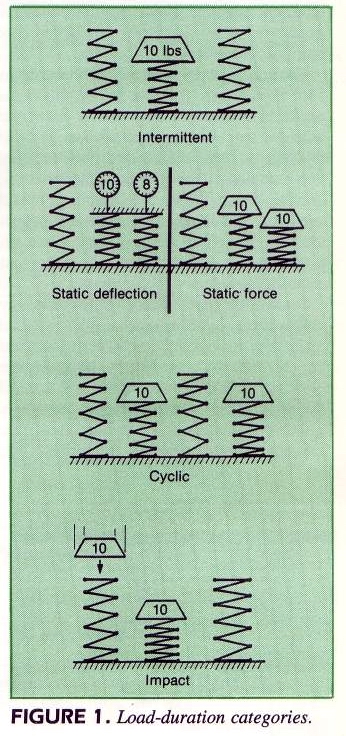
Detailed part design and evaluation is the main emphasis of this stage, and as in the Preliminary Stage, design engineering, material, and fabrication knowledge must be successfully applied. The engineering analysis can be very involved for parts with many performance or ambiguous requirements. In all cases, the need for accurate analytical results requires that performance requirements be defined. Because most polymer systems can only be assumed to be linear up to 0.5% strain, a nonlinear material analysis may be needed. A nonlinear geometric analysis is common since deflections greater than the wall thickness are often achieved. Material knowledge is essential at this stage. Because of the nonlinear mechanical behavior of all plastic materials, engineers should always work with a complete stress-strain curve tested at the end-use conditions; at the least, temperature and load duration must be specified. Temperature always affects mechanical properties. The four categories of load duration are shown in Fig. 1.
If applied loads are important, then load duration
must be known in order to use the correct properties. In addition, unlike
metals, plastics are versatile, and therefore, knowledge of flammability,
electrical, tribological, environmental, and optical properties may be
necessary. Assembly methods must be evaluated. Joining melt-processable
plastics is generally easier than joining advanced composites, but harder
than joining metals. The three categories for assembly of plastic materials
are adhesive, melt-bonded, and mechanical.
Adhesive methods cover traditional adhesives, solvents,
and hot melts. Melt bonded methods require the thermoplastic part to melt
(ultrasonics, vibration, spin, etc.). Mechanical methods are threaded assemblies,
press-fits, snap-fits, and other traditional mechanical pieces. The job
requirements dictate the category, and then the joint is engineered accordingly.
The manufacturing constraints of the process chosen
in the Preliminary Stage must be considered. For injection molding, the
design engineer must be aware of these major constraints:
residual stresses;
weldlines;
fiber orientation;
molecular orientation;
shrinkage;
cavity positioning;
gating/flow length;
cooling;
runner systems; and
part features that require slides.
None of these constraints is independent. If one is
optimized, then one or more of the others can be affected.
The first five are considered material constraints.
Major butt weldlines can reduce tensile strength by 50%. Residual stresses,
while present throughout the part, are difficult to determine, but they
can be controlled. Excessive residual stress may cause warping. Orientation
effects produce anisotropic properties. The last five are considered tooling
constraints, and must also be examined during the Engineering Stage for
a successful part design.
The kind of prototype will depend on the job requirements:
For example, if analytical techniques cannot answer all the questions posed
by the requirements, or if analytical techniques are not useful because
the requirement was poorly defined; or if a nonperforming prototype part
may be sufficient. Prototype testing is done for specific reasons, and
it can range from a very simple test to a semi production part test.
When a detailed analytical design and safety factor
selection will reduce total part testing time, testing should never be
eliminated. At the very least, testing should be done in the Manufacturing
Stage with the initial production parts. Maximum, but realistic, working
loads should be applied at the correct strain rates, at the highest temperature,
and in the presence of any expected chemicals. Constant loads should be
applied for as long as possible, but at least for 100 to 1000 hours. The
tests should represent end-use conditions as closely as possible.
The goal of the Engineering Stage is to have a completed,
production part design on paper. The drawings may be a continuation from
the Preliminary Stage if conceptual part drawings were generated. Computer
use should start at the latest in this stage. Computer generated geometries
(2-D and 3-D) and finite-element analysis (structural and flow) will expedite
this stage and the next stage.
Manufacturing Stage
Although producibility is emphasized in this stage,
design engineering and material knowledge are still required. For melt-processable
materials, producibility means the design, building, and evaluation of
a tool. This will require manufacturing equipment selection and evaluation
and possibly a flow analysis. Production part testing and a final cost
analysis are also included in this stage.
Many of the major manufacturing questions that control
the tool design should have been answered by this time since these questions
affect the detailed part design. Designing a mold is like designing an
additional part with the advantage that the performance requirements, such
as part size, part shape, and cavity number, are normally well defined.
If someone else is to design the tool, then the design
engineer must be sure that the tool designer/ custom molder understand
the project requirements and the requisite engineering subjects. For injection
molding tools, these major subjects are:
material processing and shrinkage properties;
tolerance design;
machine compatibility;
fluid flow (cooling fluids and plastic);
venting;
runner systems/gating;
heat transfer;
cooling systems;
mold types;
mold materials;
mold thermal expansion;
mold abrasion and corrosion;
mold sliding surfaces;
ejector systems;
mold construction, maintenance, and modification;
process control; and
CAD/CAE/CAM capabilities.
A flow analysis is useful during design of injection
molding tools for complex geometries. Available computer software packages
readily analyze the cavity filling sequence, enabling the pressure drop,
the temperature drop, and mold filling time to be estimated. Most important,
this estimation allows the weldline location(s), gate geometry, runner
geometry, and cavity dimensions to be analytically reviewed before the
tool is built.
A new tool should be evaluated in the production equipment.
Then, if no major problems exist with the tool, the equipment can be evaluated.
If a parallel design process - such as described in this article - is used,
the tool should not require major modifications.
For melt-processable processes, mass-flow rate is
the most important variable. For injection molding, the mass-flow rate
should be optimized for the cavity-fill sequence (high flow), and for the
cavity-pack sequence (low flow). The transfer point between these two conditions
is also important. For a given shot volume, melt temperature, and mold
temperature, mass-flow rate is tweaked by pressure levels and pressure
duration's. Flow analysis results should be used as a starting point. Because
part performance greatly depends on how the plastic fills the cavity, the
goal must be to achieve a controlled process. Some form of part testing/evaluation
should be conducted on the first workable parts produced. If any agency
approvals require the entire part, then testing should start at that point.
Any needed modifications to the design or material should be performed,
and new workable parts produced and retested. The goal of the Manufacturing
Stage is to produce quality parts that are ready for market.
Plastic Materials
Plastics span a wide range of material behaviors, primarily because of the addition of reinforcement fibers, fillers, and other additives. Materials can be divided into three general categories, as shown in Fig. 2 through 4. A large deformation with a relatively small increase in load for some portion of the stress strain curve is defined as yielding (Fig. 2).
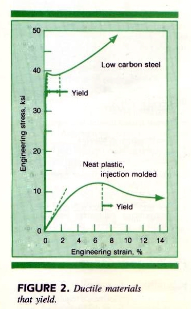
Ferrous metals experience a sharp yield point, while
many neat plastics experience a more gradual yield region. Strengths are
defined at the yield point, the highest point, and at fracture for ferrous
metals. For plastics, only the highest point is defined as the tensile
strength; if it occurs at yield, it is defined as the tensile strength
at yield, and if it occurs at fracture, it is defined as the tensile strength
at break.
Modulus is defined as the initial slope of the stress-strain
curve. For ferrous metals, the initial slope defines a large portion of
the curve up to high stress levels. However, for neat plastics, the initial
slope defines only a small portion of the curve.
Some materials do not yield, yet they are ductile
(Fig. 3).
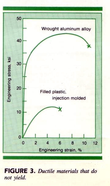
For such metals, a yield strength is defined at a point
after the linear portion. A yield strength cannot be defined for the neat
and filled plastics in this category. Instead, the highest point on the
curve is the defined tensile strength.
All reinforced and some filled plastics fall into
the third category - brittle materials (Fig. 4).
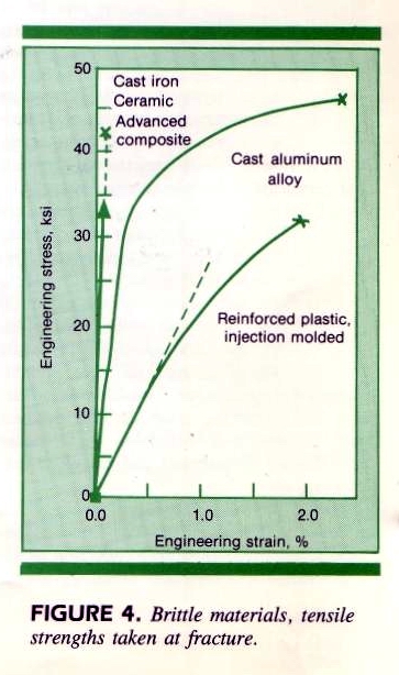
The important defined tensile strength is at fracture.
Although the initial slope defines a greater portion of the curve for reinforced
materials, the portion is still only about one third of the curve.
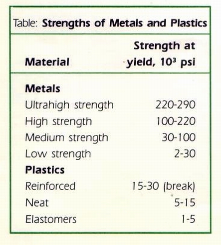
The strength ranges of plastic materials and metals
are compared in the Table.
Initial slopes, and thus modulus ranges, are shown in Fig. 5.
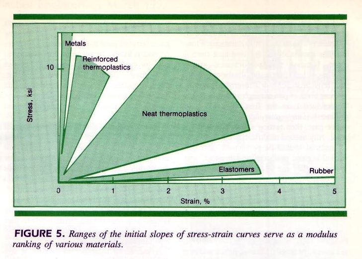
Note that metals offer many strength options but are limited with regard to modulus; plastic materials offer the opposite.
Part Tolerances
Tolerances influence a plastic part in many ways -
from necessitating secondary manufacturing steps to rendering a part completely
impractical to produce economically. While this is true for any manufactured
part, the influence of tolerances on cost is harder to assess in the design
process for melt-processable materials because of the many variables. For
injection molding, these variables can be grouped into six categories:
material shrinkage; part geometry; gating; tool quality; tool tolerance;
and processing.
Tool tolerances are unique to the tool manufacturing
method and are usually held constant for any dimension. It is not trivial
to realize that part tolerances cannot be tighter than tool tolerances.
Processing variables are optimized to produce the best overall part and
not to achieve a particular tolerance. Therefore, if normal tool tolerances
are held and if processing variables are kept constant (closed loop controls
are recommended), four variable categories remain that control injection
molding tolerances.
A successful tolerance evaluation at any point in
the design process must involve design engineering, material, and fabrication
knowledge. Material knowledge is necessary for understanding material shrinkage
for a particular thickness and flow distance, and for understanding the
effects of reinforcements, fillers, and additives on shrinkage.
Evaluating the effects of part geometry requires design
engineering knowledge. For example, the tolerance values and the tolerance
type (standard vs. geometric) must be realistic and related to the dimension
size and type. Dimensions across parting lines and those that restrict
material shrinkage are special. Wall thickness is important because of
shrinkage, and standard injection molding guidelines, such as uniform wall,
radii, and draft, all affect tolerances.
Fabrication knowledge is required for determining
gating and tool quality. Gate location and number are extremely important
because they control the flow distance to the toleranced dimension. They
are also important factors in establishing an even pressure distribution
in the cavity - a balanced and proper (hot vs. cold) runner system is the
other - and in controlling fiber orientation. Flow distance and weldlines
should always be minimized, as should anisotropic fiber orientation for
some flatness tolerances. Gate size and type are also important. Achieving
the set tolerances depends on a quality tool, one that has proper cooling
for even heat transfer, proper venting, and sufficient size for minimal
deflection, and is made of the correct materials.
Safety
Safety refers to the ability of a part to perform its
proper function for its service life without failure. Function, service
life, and part failure must be defined. Factor of safety definitions, failure
theories, and prototype and production part testing are also involved.
Factors-of-safety may be defined in many ways; however,
they basically relate what
is permissible or allowable to what will cause failure.
A factor-of-safety can be applied in three basic ways. The entire factor
can be applied to a material property such as strength; or the entire factor
can be applied to the loading; or separate factors can be used for each
load and a material property.
The latter case is the most useful because each load
can be investigated and then a factor-of-safety applied to determine an
absolute maximum. Each maximum load is then used in the stress analysis
such that the geometry and boundary conditions produce an allowable stress.
The allowable stress limit is determined by applying a strength factor-of-safety
to the material strength at end-use conditions.
The load factors-of-safety can be determined in the
traditional manner. The strength factors-of-safety for plastic materials,
however, are often difficult to ascertain. Because the strength of a plastic
is not a material constant, a statistical distribution of strength under
end-use conditions is usually impossible to determine.
Strength is affected by temperature, strain rate,
load duration, weldlines, anisotropy, lot variations, process variations,
and residual stresses. Consequently, design engineering knowledge is needed
to understand end-use conditions, for example, temperature, strain rate,
and load duration; and fabrication knowledge is needed to understand weldline
situations, anisotropic effects, residual stresses, and process variations.
Material knowledge is most important because the better
the material behavior at the end-use conditions is understood, the more
accurately the factor-of-safety can be established, resulting in an optimum
part geometry. The poorer the definition and the greater the number of
unknowns, the larger the factor-of-safety required. Variables such as lot
and process variations and residual stresses can be studied and controlled,
but never quantified. Therefore, a minimum factor of safety of two is recommended,
even when the application has been carefully analyzed.
Factor-of-safety definition is an important step in
the design effort that occurs in the Engineering Stage. Proper safety factor
definition will reduce testing time and minimize rework, but it cannot
be accomplished without the three fundamentals - design engineering, material,
and fabrication knowledge.